


Table of Contents
Creating a negative from a shape is a practical way to turn a digital model into a reusable mold, insert, forming tool, or casting aid. Instead of printing the final object directly, you create a cavity that captures its surface and dimensions.
The process usually starts with a positive model. You place that model inside a block or container shape, subtract it with a Boolean operation, and refine the resulting cavity for printing. The workflow is useful for silicone casting, resin casting, soap molds, protective inserts, packaging prototypes, vacuum-forming tools, and small-batch manufacturing.
A printable negative needs more than a hollow space. It also needs suitable wall thickness, release angles, clean geometry, and a realistic assembly plan. This guide explains how to make negatives from a shape to 3D print and how to avoid the errors that make molds difficult to print or use.
What Is a Negative Shape in 3D Printing?
A negative shape is the inverse of an object. It represents the empty space that the original object would occupy inside another solid body.
When you press a shape into clay, the indentation is a negative. In 3D modeling, the same idea is created digitally. A positive object is removed from a surrounding block to form a cavity.
Differences Between Positive and Negative Geometry
Positive geometry represents the physical object itself. A printed figurine, bracket, bottle cap, or product enclosure is positive geometry because the printed material forms the final part.
Negative geometry represents the cavity around that object. It is usually printed as part of a mold, insert, or tool. The cavity can receive silicone, resin, wax, plaster, soap, or another suitable casting material.
The difference is simple:
-
A positive model creates the object.
-
A negative model creates the space needed to reproduce the object.
A single project may use both. For example, you can print a positive master pattern and pour silicone around it to produce a flexible negative mold. You can also model the negative digitally and print a rigid mold directly.
How Negative Molds Capture a Shape's Cavity
A negative mold reproduces the external surface of a positive model. Every visible feature on the original object becomes an internal feature inside the mold.
Raised text on a positive model becomes recessed text in the negative. A recessed logo becomes raised geometry inside the mold. Rounded edges, small grooves, surface textures, and undercuts also transfer into the cavity.
The accuracy of the finished cast depends on the quality of the negative model. A rough cavity can leave visible marks. An incomplete cavity can create missing details. A cavity with poor alignment can produce a distorted part.
Before printing, inspect the cavity from several angles. Check whether the shape can be released after casting. A cavity can be geometrically accurate but still impractical to use if the finished part becomes trapped inside the mold.
Real-World Examples of Negative Forms
Negative forms appear in many everyday products and manufacturing workflows.
A silicone mold for a candle contains the negative shape of the candle. A protective packaging insert holds a product inside a fitted cavity. A soap mold defines the size and surface pattern of each bar. A vacuum-forming tool shapes a heated sheet into a controlled contour. A custom tray can hold tools, components, collectibles, or electronic devices in precisely sized recesses.
Negative models also support product development. A design team can create a test mold for a new handle, gasket, decorative part, or packaging insert before investing in conventional tooling.
Why Create Negative Models for 3D Printing?
A negative model turns a single digital file into a repeatable production tool. This can be more practical than printing every final object separately.
The right workflow depends on the casting material, target quantity, surface quality, and expected use. A rigid printed negative may work for some low-temperature applications. A printed positive master may be better when you need a flexible silicone mold.

Reproducing Complex Shapes Efficiently
Some objects are difficult to reproduce with basic manual molding methods. They may contain custom dimensions, detailed textures, curved surfaces, or several connected features.
A digital negative captures these details consistently. Once the file is complete, you can print another mold section without rebuilding the design manually.
This is useful for customized work. A workshop can change a name, logo, dimension, cavity depth, or product layout inside the CAD file. The updated negative can then be printed as a new version.
Digital modeling also makes iteration easier. When a cavity is too tight or a release angle is insufficient, you can modify the source file and print a corrected mold.
Saving Time and Cost in Small-Batch Production
Negative molds are useful when a workshop needs to reproduce the same shape several times without rebuilding each part from scratch.
A printed mold can reduce setup time for prototypes, limited product runs, personalized orders, and design validation. It also helps teams test a concept before committing to more expensive tooling.
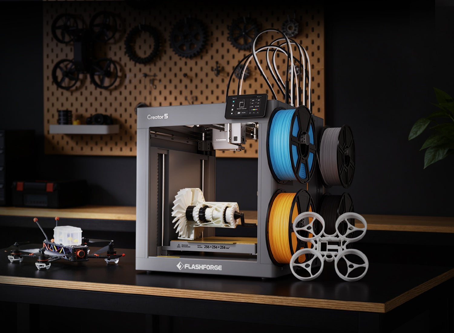
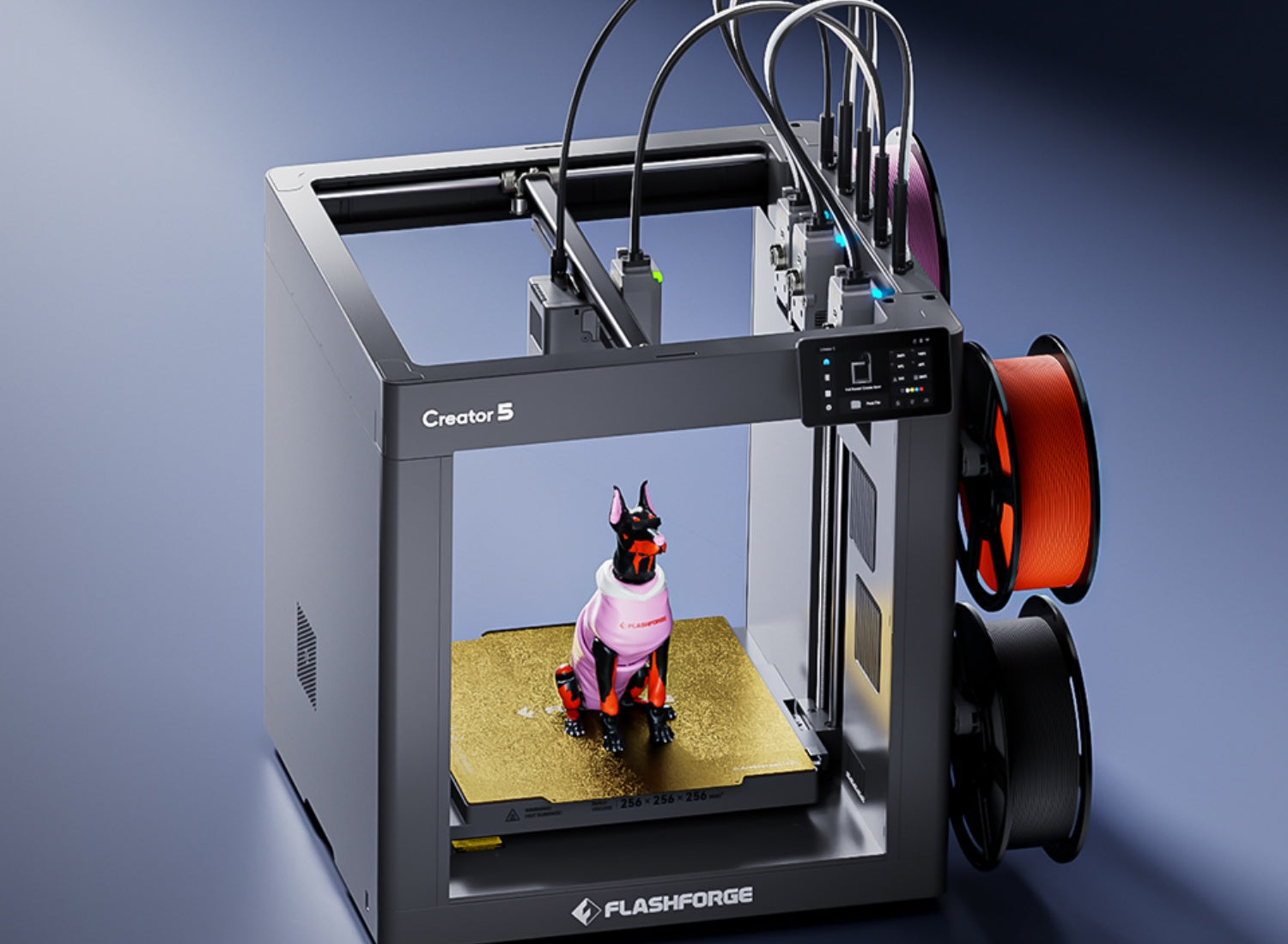
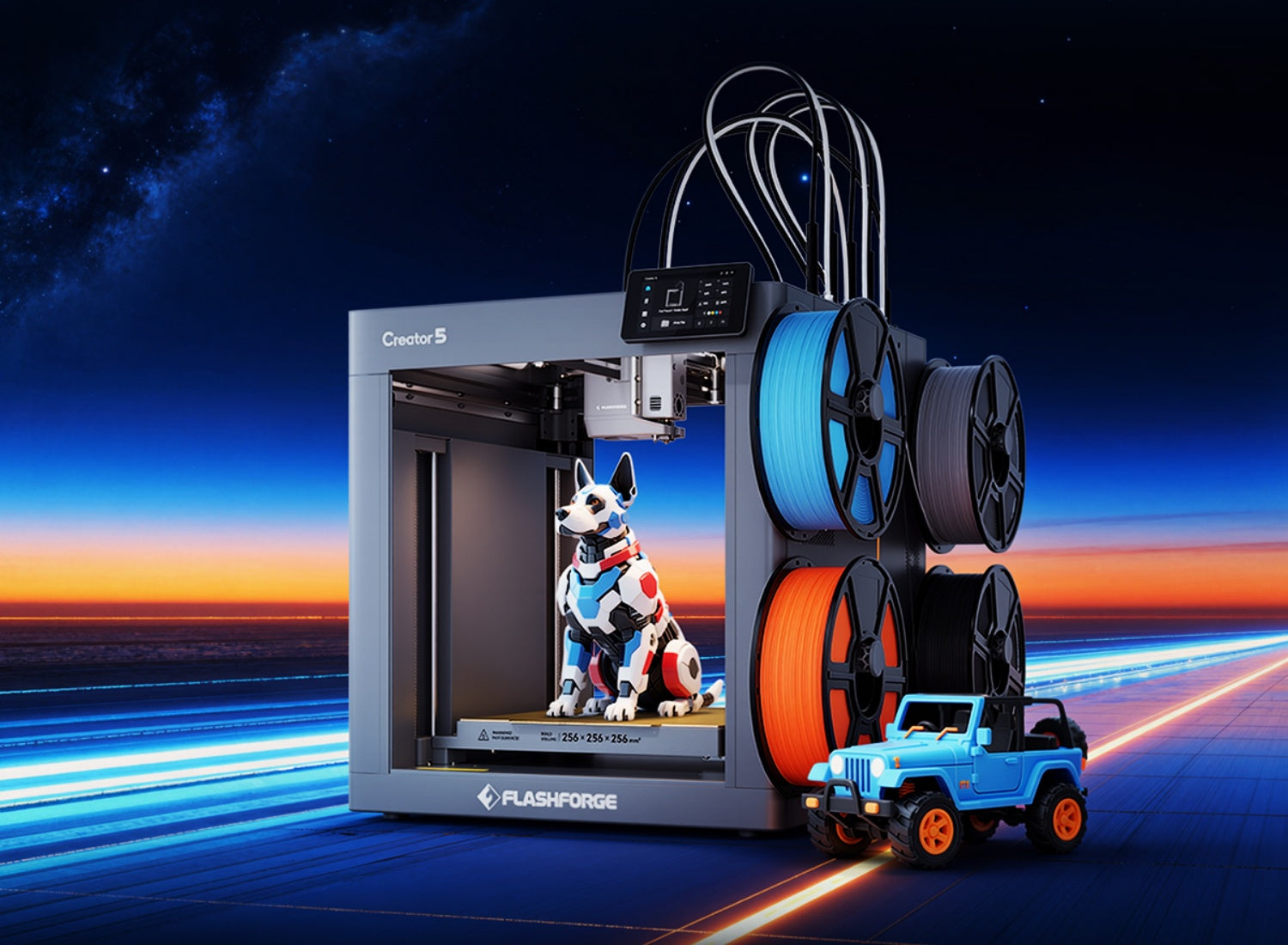
Printing efficiency matters when a mold design includes several sections or materials. The Flashforge Creator 5 (C5) uses four independent toolheads and avoids purge waste during material switching. This makes it a practical option for multi-part molds, labeled mold sections, and small-batch prototyping workflows where frequent material changes could otherwise consume extra filament.
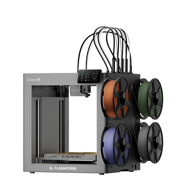
Flashforge Creator 5 4-Toolheads Multi-Color 3D Printer | 500% Faster, Zero Purge Waste
For a closer look at how extrusion systems affect material waste, support workflows, and multi-material FDM printing, read What Is a Dual Extruder 3D Printer? Types, Benefits, and Best Uses Explained.
Enabling Casting, Forming, and Molding Workflows
Negative models connect 3D printing with other manufacturing methods.
A printed negative can hold casting silicone or resin. A printed master can help create a flexible mold. A rigid tool can support vacuum forming. A custom insert can hold a product inside protective packaging. A two-part mold can help validate a gasket, handle, decorative component, or enclosure detail.
The goal is not always to replace conventional manufacturing. In many cases, the value comes from faster iteration. A small team can test dimensions, identify release problems, and improve the design before moving into a larger production run.
Choose the Right 3D Modeling Software
The best modeling software depends on the object and the workflow.
Simple molds need basic solid modeling tools. Complex molds may require reliable Boolean operations, parting-line control, mesh repair, and multi-part assembly planning. The software should match the level of precision required by the project.
Beginner-Friendly CAD Tools
A beginner-friendly CAD tool should make it easy to create solids, adjust dimensions, align objects, and subtract one shape from another.
For a basic negative mold, you need only two primary objects: the positive model and the surrounding block. After positioning the positive model, you apply a Boolean difference operation to remove its volume from the block.
Beginners should start with simple shapes. A rectangular tray with one product cavity is easier to test than a complex multi-part mold. Once the workflow is clear, you can add draft angles, alignment pins, channels, and separate mold sections.
Professional Software for Mold and Boolean Operations
Professional CAD software provides more control over parametric dimensions, assemblies, surfaces, draft analysis, and mold separation.
These capabilities matter when a negative must fit an existing product, support repeated casting, or connect with another mold section. Parametric modeling is especially useful because dimensions can be updated without rebuilding the entire model.
For example, a packaging insert may need several cavity sizes for different product variants. A parametric file lets you adjust the cavity width, depth, spacing, and wall thickness while preserving the overall design logic.
Mesh Editing vs Parametric Modeling Workflows
Parametric modeling works best when dimensions and repeatability matter. It is suitable for trays, enclosures, brackets, packaging inserts, tooling prototypes, and mechanical mold sections.
Mesh editing is more useful for organic objects, scans, decorative patterns, and irregular surfaces. A scanned figurine or handmade object may arrive as a mesh rather than a clean CAD solid. In that case, the model may need smoothing, repair, simplification, and alignment before subtraction.
The choice also depends on the source file. A clean CAD model is easier to modify parametrically. A scanned object often needs mesh editing before it can become a printable mold cavity.

Free vs Paid Design Programs
Free design programs can handle many basic negative-model workflows. They are suitable for learning Boolean subtraction, repairing simple meshes, and creating basic one-part or two-part molds.
Paid software becomes more valuable when the project requires advanced assemblies, surface controls, version management, manufacturing documentation, or repeated client work.
The software price is not the only factor. Choose a program that supports the file types you receive and the editing tools you need. A simple tool with a clear workflow is often better than a complex program that slows down basic mold design.
How Do Boolean Operations Work in 3D Modeling?
Boolean operations combine or modify solid shapes.
The three common operations are union, intersection, and difference. Union joins two shapes. Intersection keeps the overlapping area. Difference subtracts one shape from another.
The official Blender Boolean Modifier documentation shows how Boolean operations can combine meshes and create difference geometry.
Boolean Difference Workflow and Function
A Boolean difference operation needs two objects:
-
A base block or container.
-
A positive model that acts as the cutting shape.
Place the positive model inside the block. Then subtract the positive model from the block. The remaining solid contains a cavity with the inverse shape of the original object.
Keep a copy of the positive model before applying the operation. This makes it easier to adjust the cavity depth, position, and clearance later.
Why Subtraction Creates a Negative
The positive model defines the volume that will be removed.
When the software subtracts that volume from the surrounding block, it leaves empty space behind. That empty space is the negative.
The cavity can match the positive model exactly, but an exact match is not always the best choice. A usable mold may need additional clearance, draft angles, vents, pouring channels, or a parting line. These features help casting material enter the mold and help the finished part release cleanly.
Common Problems in Boolean Subtraction
Boolean subtraction can fail when the geometry is incomplete or overly complex.
A common problem is an open mesh. If the positive object has holes or missing surfaces, the software may not recognize it as a solid volume. Intersecting faces, duplicate surfaces, inverted normals, very thin walls, and tiny disconnected fragments can also cause errors.
Another issue appears when the positive object only touches the edge of the base block. A shallow or ambiguous intersection can create unstable geometry. Move the object slightly deeper into the block and check whether the subtraction becomes cleaner.
After applying the Boolean operation, inspect the cavity carefully. Look for missing faces, unexpected holes, and thin walls around the edges of the block.
Repairing Non-Manifold and Broken Geometry
A printable negative needs manifold geometry. This means the model should form a closed, physically possible solid.
Run a geometry check before and after Boolean subtraction. Close holes, remove duplicate surfaces, delete disconnected fragments, and correct inverted normals. If the repaired mesh remains unstable, return to the source model and simplify it before trying again.
A clean source model produces a more reliable mold. Repeatedly repairing an exported mesh may solve a short-term problem, but it makes future edits harder.
Step-by-Step Guide to Creating a Negative Shape
The following workflow works for trays, basic casting molds, product inserts, and simple manufacturing aids.
More advanced molds may need additional vents, channels, alignment features, or multiple sections. However, the main logic remains the same.
Import or Create the Original 3D Model
Begin with the positive model.
You can create the model in CAD software, import an existing file, or build a mesh from a 3D scan. The source model should match the dimensions and surface details you want to reproduce.
Check the scale before moving forward. Confirm the length, width, height, and orientation. Remove unnecessary internal geometry. Repair open surfaces and disconnected features.
For scanned objects, simplify noisy areas before subtraction. Excessive surface noise can create a rough cavity and increase slicing time.
Design a Base Block or Container Shape
Create a block around the positive model.
The block must be large enough to contain the cavity while leaving suitable walls around the sides and bottom. Thin walls can crack during printing, casting, or demolding.
The shape does not need to be rectangular. A circular object may fit better inside a cylindrical mold. A tray may need rounded corners. A packaging insert may use a larger plate with several cavities.
Leave enough external material to keep the mold stable. If the mold will be clamped, add flat outer surfaces. If it is filled with liquid, make sure the block remains level during use.
Apply Boolean Subtraction to Form the Cavity
Position the positive model inside the block. Align it carefully. Then apply a Boolean difference operation.
The cavity should appear inside the block after subtraction.
Inspect the opening. Check whether the cavity is deep enough to capture the required shape. Confirm that the walls remain intact. Look for trapped areas that could prevent release.
Keep the original positive model in a separate layer or file. You may need it again when creating a second mold half, adjusting the fit, or testing another version.
Check Depth, Alignment, and Surface Accuracy
A usable negative needs accurate placement.
Check the cavity depth first. A shallow cavity may fail to capture important details. An overly deep cavity may make demolding difficult.
Then inspect the alignment. The positive model should sit in the intended position inside the block. Packaging inserts need even spacing. Two-part molds need matching edges and registration points.
Finally, review the surface. Small gaps, rough scans, or broken mesh areas can appear inside the cavity. These defects may transfer into the cast object.
Export a Clean, Printable Mesh
Export the completed mold in a format supported by your slicer. STL is suitable for many single-material molds. A format such as 3MF can be useful when the project includes multiple bodies or materials.
Before printing, import the exported model into the slicer and inspect the toolpaths layer by layer.
Check the first layer, cavity walls, thin sections, overhangs, internal surfaces, and support placement. A negative mold may appear correct in CAD but still contain toolpath problems that only become visible after slicing.
A negative mold may appear correct in CAD but still contain toolpath problems that only become visible after slicing. For a more detailed explanation of model importation, slicing parameters, and G-code generation, read the Flashforge guide to Orca and Orca-Flashforge slicer software.
Design Considerations for Printable Negative Molds
A negative mold needs to print cleanly and release the finished part without damage.
The most important design decisions involve draft angles, undercuts, wall thickness, and mold separation.
Adding Draft Angles for Easier Release
A draft angle is a slight taper on a vertical wall. It helps the finished part slide out of the mold.
Straight walls can grip the cast object, especially when the cavity is deep. A small taper reduces friction and makes release easier.
The required draft depends on the shape, depth, surface texture, and casting material. A shallow tray may need only a modest adjustment. A deep, rigid mold may need more careful planning.
Do not add a draft automatically to every feature. Some surfaces need to remain dimensionally accurate. Focus on the walls that affect release.
Preventing Undercuts and Trapped Geometry
An undercut is a feature that prevents the cast part from leaving the mold in a straight direction.
A flexible silicone mold can handle some undercuts because the mold bends during release. A rigid printed mold cannot flex as easily. Large hooks, deep grooves, internal lips, and enclosed cavities can trap the finished part.
Review the mold from the release direction. Ask whether the part can move out of the cavity without colliding with the walls.
When the answer is no, change the geometry or divide the mold into multiple sections.
Wall Thickness and Structural Strength
Mold walls must survive printing, filling, handling, and release.
Thin walls can crack when the mold is removed from the build plate or when the cast part is pulled out. Large flat walls can also deform if they lack reinforcement.
Choose the wall thickness according to the mold size, material, and expected reuse. Add ribs where a large surface needs support. Use thicker walls around alignment holes, clamps, and edges.
For low-volume prototypes, the mold may only need to survive a few uses. Repeated production requires a more conservative design.
Splitting Multi-Part Molds for Complex Objects
A one-part mold works when the object can be removed in one direction. Complex shapes often need two or more mold sections.
Choose a parting line that reduces trapped geometry and protects visible surfaces. Add alignment pins or sockets so the sections fit together consistently. Leave room for clamps when the mold needs pressure during casting.
Splitting the design can reduce support requirements, improve release, and make large objects easier to print.
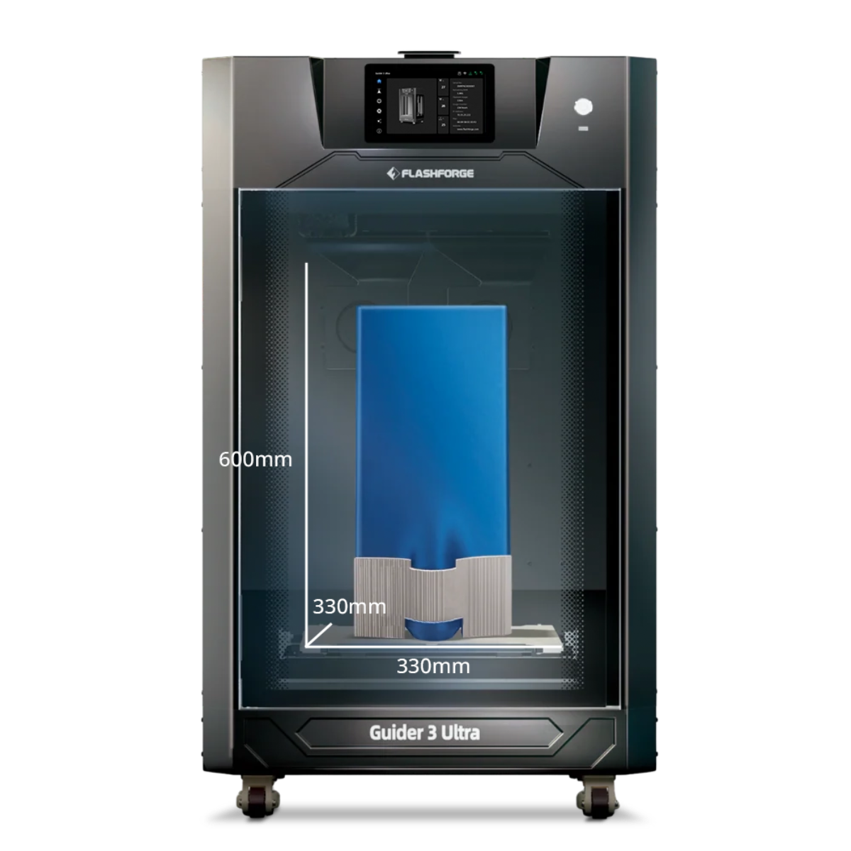
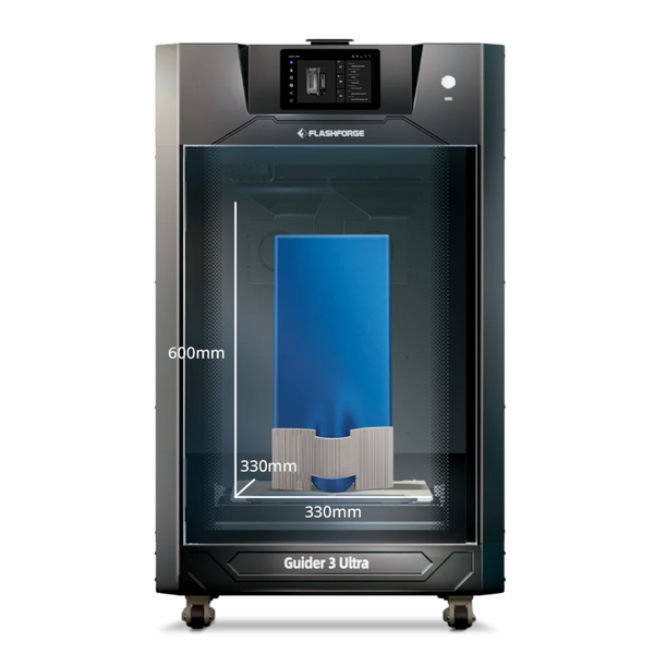
For larger master patterns or mold components, the Flashforge Guider 3 Ultra provides a maximum build volume of 330 × 330 × 600 mm in single-extruder mode. Its dual-extruder system also supports soluble-support workflows for geometry that is difficult to print cleanly with standard supports.
Best Use Cases for 3D Printed Negative Shapes
Negative models are useful whenever a project needs a repeatable cavity.
The right printing method and material depend on the casting medium, heat exposure, pressure, required finish, and target quantity.
Silicone and Resin Casting Molds
Printed negatives can support silicone and resin casting for prototypes, decorative parts, gaskets, handles, small accessories, and custom components.
A rigid printed mold is useful when the shape releases easily. A flexible silicone negative may be better when the original object contains undercuts or fine details.
Test the material combination before committing to a full mold. Casting materials can react differently with printed surfaces, coatings, and release agents.
When casting silicone against a printed resin surface, curing matters. Silicone manufacturer Smooth-On explains that platinum-cure silicone can be inhibited by an SLA model that has not been fully UV cured. Its official silicone mold FAQ recommends completing the curing process before molding.
Custom Packaging and Protective Inserts
A negative insert can hold a product securely inside a box, case, tray, or display package.
This is useful for tools, electronics, collectibles, medical-device prototypes, and product samples. The cavity can follow the shape of the object while leaving space for fingers, cables, straps, or accessories.
Packaging inserts benefit from parametric modeling. When product dimensions change, you can update the cavity without redesigning the entire tray.
Vacuum Forming and Manufacturing Tooling
Negative models can also support vacuum-forming patterns, manufacturing aids, and engineering-tooling prototypes.
Vacuum forming may use a positive or negative tool depending on which surface needs better definition. In both cases, the printed tool must match the operating temperature and pressure of the process.
Choosing the right 3D printer filament becomes more important when the part needs improved heat resistance or dimensional stability. If the workflow requires ABS, an ABS 3D printer with an enclosed and temperature-controlled printing environment can help reduce warping during production.
The Flashforge Creator 5 Pro (C5P) combines four independent toolheads with a fully enclosed frame and an actively heated chamber up to 65°C. Its broader filament support makes it relevant for selected engineering-material prototypes and small-batch tooling applications.
Always confirm that the selected filament can tolerate the actual process conditions. A printed prototype tool is not automatically suitable for every forming temperature or production cycle.
Jewelry, Soap, and Food-Safe Molds
Negative molds can support jewelry prototypes, soap molds, chocolate molds, and other small decorative forms. However, food-contact applications need additional care.
A filament or coating should not be treated as food-safe based only on a marketing label. The U.S. Food and Drug Administration explains that food-contact substances include materials used in packaging, processing equipment, food-preparation surfaces, and cookware. Their safety depends on the intended use.
The FDA also states that the regulatory status of a food-contact material depends on the substances that make up the article and their potential migration into food. Review the FDA guidance on food-contact materials and confirm the selected material, coating, release agent, cleaning method, temperature, and reuse conditions before making a mold for food contact.
For many projects, a practical approach is to use the printed object as a master pattern and create the final food-contact mold from a suitable compliant material.
DIY Prototyping and Engineering Applications
Negative models help makers and engineering teams test ideas quickly.
A printed negative can validate a product insert, seal, gasket, grip, enclosure detail, or assembly aid. It can also reveal problems that are difficult to identify on a screen, such as poor release, thin walls, misaligned features, and trapped geometry.
The best 3D printer for a negative-mold workflow depends on the size of the mold, the required material, the expected number of uses, and the complexity of the cavity. Start with a small test. Confirm the dimensions and release behavior before printing a larger tool or producing a batch of cast parts.
Conclusion
Creating a negative from a shape is a practical extension of 3D modeling. The process starts with a positive object and a surrounding block. A Boolean difference operation removes the positive volume and leaves a printable cavity.
The basic workflow is simple, but the design details matter. A usable mold needs clean geometry, suitable walls, realistic release angles, and a clear strategy for undercuts. Complex objects may need multiple mold sections. Casting materials may also require testing, curing, coatings, or release agents.
Start with a simple negative. Print a small version. Test the fit and release. Then refine the model before moving into a larger or repeated workflow.
FAQ
How to turn an object into a 3D print?
You can create a printable model by drawing the object in CAD software, sculpting it digitally, or capturing its shape with a 3D scanner or photogrammetry workflow.
After creating the model, check the scale, repair the geometry, and export the file in a format supported by your slicer. Import the file, select the printer and material profile, add supports where needed, and preview the toolpaths before printing.
When the goal is a negative mold, place the digital object inside a block and subtract it with a Boolean difference operation.
What am I not allowed to 3D print?
There is no single universal list. The rules depend on your country, state, product category, and intended use.
Do not print or sell designs that you do not have the right to reproduce. The U.S. Copyright Office explains that sculptures, illustrations, technical drawings, and other visual works can receive copyright protection. The USPTO also explains that words, phrases, symbols, and designs can function as trademarks when they identify goods or services.
You should also avoid regulated, restricted, or safety-critical items unless you understand the applicable rules and have the required approvals. Check local law and obtain professional advice when the intended use creates safety or compliance risks.
When should I split a mold into multiple parts?
The right mold structure depends on the release direction, surface details, and complexity of the original shape. A simple cavity may only need one printed section, while objects with undercuts or enclosed features often require a mold that opens from several directions.
| Mold Structure | Best For | Main Advantage | Key Design Consideration |
| One-part mold | Shallow trays, simple cavities, packaging inserts, and objects with a clear release direction | Easy to design, print, and fill | Avoid deep undercuts and trapped geometry |
| Two-part mold | Handles, figurines, soap molds, and objects with details on several sides | Captures more complex surfaces while keeping assembly manageable | Add a clear parting line, alignment pins, and a suitable filling opening |
| Multi-part mold | Complex prototypes, detailed decorative parts, and objects with several undercuts | Allows the finished part to release from multiple directions | Keep the number of sections practical and confirm that each section can be assembled consistently |
| Flexible mold made from a printed master | Organic shapes, textured objects, and parts with moderate undercuts | Flexible mold material can simplify demolding | Test material compatibility and complete any required curing or sealing before casting |
What is the best material for 3D printing molds?
The best material depends on the casting medium, temperature, pressure, surface finish, and expected number of uses.
PLA and PETG can work for basic low-temperature prototypes and simple molds. More demanding tooling may need a material with improved heat resistance or dimensional stability. Engineering filaments can be relevant when the process conditions require them.
Do not choose a material based only on its category name. Check the filament specifications and test the mold under realistic conditions before using it for repeated production.
Do I need draft angles on every 3D-printed mold?
Not always.
A shallow flexible mold may release without a noticeable draft angle. A deep, rigid cavity usually benefits from a slight taper. Draft angles become more important when the walls are tall, the surface is textured, or the casting material grips the mold.
Review the release direction before printing. Add a draft where it improves demolding without changing critical dimensions.
Can I use a 3D-printed mold for silicone casting directly?
Sometimes, but test the specific material combination first.
The mold surface, printing material, curing process, coating, and silicone chemistry can affect the result. Some surfaces may need a suitable release agent. Others may require sealing or additional curing.
Smooth-On notes that a release agent can make demolding easier and recommends a small test when material compatibility is uncertain. Its Mold Star product guidance also explains that performance should be tested for the intended project.
For resin-printed molds or master patterns, complete the required post-curing process before casting silicone. A small compatibility test can prevent a failed full-size mold.