


Table of Contents
Creating a 3D model for printing requires more than drawing an object on a screen. A design may look complete in CAD software but still fail during printing because the walls are too thin, the dimensions are inaccurate, or the geometry contains hidden errors.
A printable model needs clear dimensions, solid geometry, suitable wall thickness, and a structure that matches the printing process. Functional parts also need realistic clearances. Large objects may need to be divided into smaller sections. Multi-color models should use separate bodies so each color or material can be assigned correctly in slicer software.
This step-by-step guide explains how to create 3D models for printing, validate the geometry, export the file, and prepare the model in a slicer before starting a print.
How 3D Modeling Works for 3D Printing
A 3D model is a digital representation of a physical object. It defines the shape, dimensions, surfaces, and internal features that a printer will reproduce layer by layer.
The basic workflow follows five stages:
- Create the model in CAD, sculpting, or mesh-editing software.
- Check whether the geometry is complete and printable.
- Import the file into Slicer software.
- Convert the model into toolpaths and printer instructions.
The design software determines what the object should look like. The slicer determines how the printer should build it.
For FDM printing, the slicer divides the object into horizontal layers and calculates the walls, infill, supports, travel moves, and extrusion paths. The printer then deposits melted filament layer by layer until the object is complete.
The Flashforge guide to slicer software explains that slicing includes model importation, parameter configuration, and G-code generation. Layer height, infill density, print speed, and temperature settings all affect the final result.
The same model can produce different results depending on the nozzle size, filament, orientation, and slicer settings. A decorative PLA model may need structural changes before it can work as a functional component.
Designing for 3D printing, therefore, means considering the manufacturing process from the beginning. A successful model should not only look correct in the software. It should also be practical to print, assemble, and use.
How Do You Create a 3D Model for 3D Printing Step by Step?
A printable model should begin with a clear purpose. Decide whether the object is decorative, functional, wearable, or part of an assembly. This determines the dimensions, wall thickness, tolerances, and finishing process.
Start with Basic Shapes and Accurate Dimensions
Begin with the simplest geometry that defines the object.
Most functional models can be built from boxes, cylinders, spheres, cones, and extruded sketches. A storage bin may start as a rectangular shell. A bracket may begin with a flat plate and two holes. A product enclosure may start as a box with rounded corners.
Define the overall length, width, and height first. Add the main openings, mounting points, and contact surfaces before creating decorative details.
Use calipers when the model needs to fit an existing object. Hole diameters, clip widths, wall thicknesses, and clearances are difficult to measure accurately with a basic ruler. For replacement parts, also record hole depth, center-to-center spacing, contact surfaces, and installation direction.
Reference geometry improves accuracy. Centerlines, construction sketches, reference planes, and anchor points help keep the design aligned. When a printed part needs to connect to another object, model the connection area first.
Do not assume the printed result will match the CAD dimensions perfectly. Filament, nozzle size, orientation, and slicer settings can introduce small dimensional differences. Print a test section before producing the complete part.
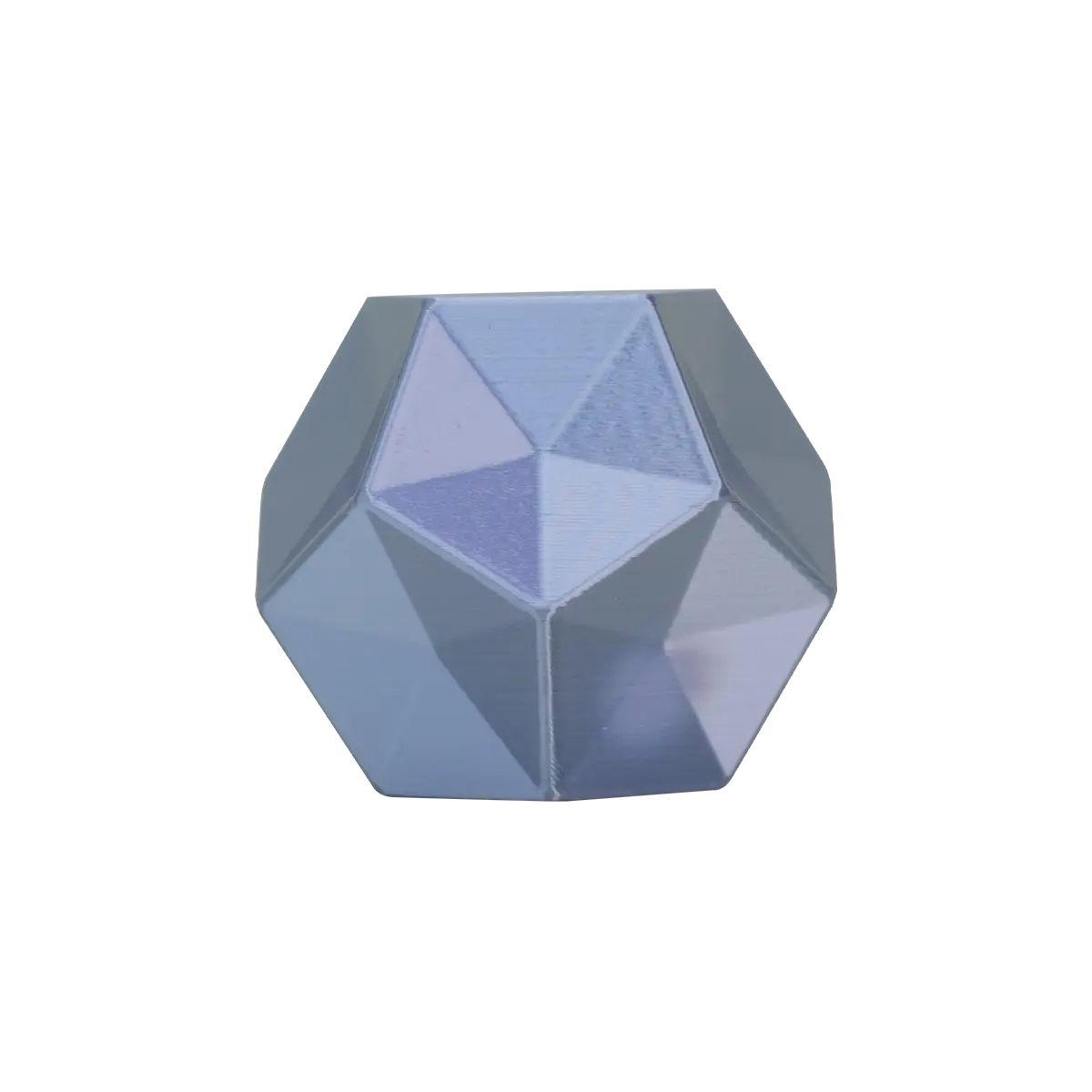
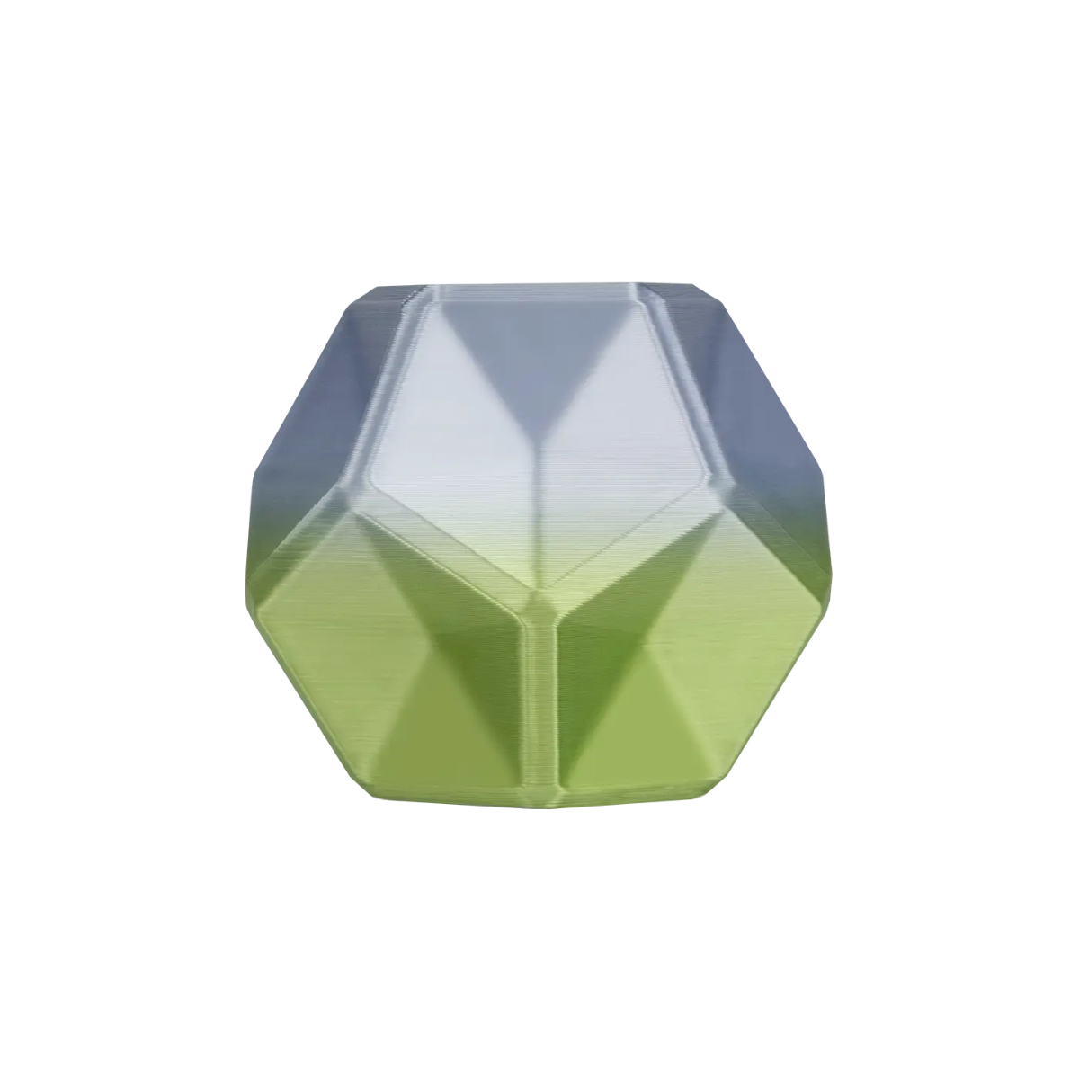
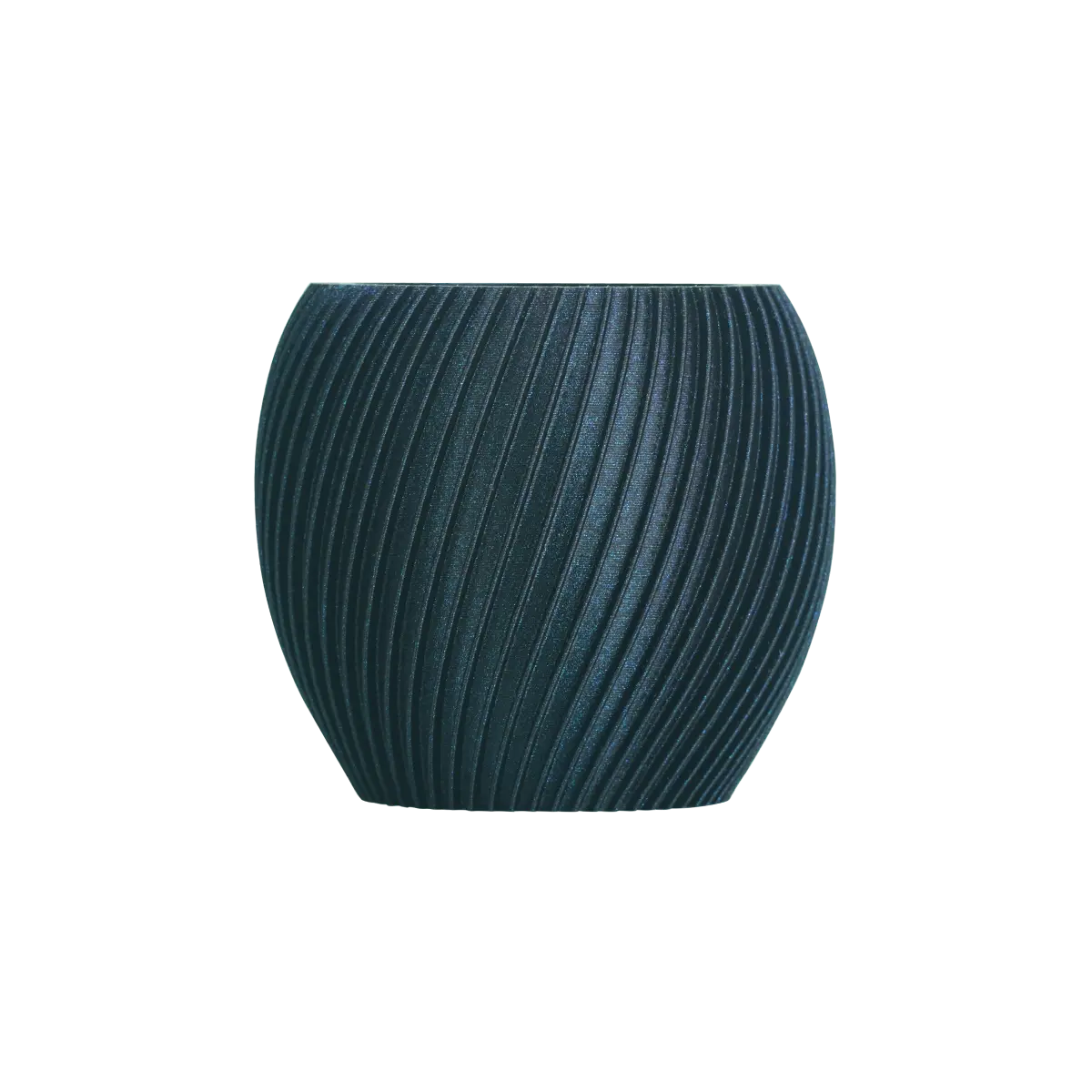
Add Details Without Overcomplicating the Design
Add details only after the main dimensions are correct.
Embossed text, surface patterns, ribs, fillets, chamfers, and rounded edges can improve the appearance or function of a model. However, unnecessary details increase slicing time and print complexity.
Use chamfers where parts need to slide together. Add ribs where thin walls need reinforcement. Use rounded edges when a wearable object needs a more comfortable surface. Add alignment features when several parts must be assembled after printing.
Avoid details that are smaller than the printer can reproduce consistently. A thin embossed logo may disappear after slicing. A narrow groove may close during extrusion. A dense decorative texture may increase print time without improving the final result.
Check Wall Thickness and Structural Stability
A visible surface in CAD is not automatically a printable wall. It needs enough thickness to survive printing, handling, and use.
Minimum wall thickness depends on the nozzle diameter, filament, layer height, orientation, and expected load. There is no single value that works for every project.
The Flashforge introduction to FDM 3D printing explains that walls should generally be at least two to three times the nozzle diameter. For a typical 0.4 mm nozzle, this gives a practical starting range of 0.8 to 1.2 mm.
Treat this range as a baseline rather than a fixed rule. A decorative shell may remain relatively light. A bracket, fixture, or load-bearing component may need thicker walls, additional perimeters, reinforcing ribs, or a stronger filament.
Pay close attention to narrow joints, screw holes, clips, unsupported features, corners, and areas where force changes direction. When strength matters, test the printed part under realistic conditions.

Prepare Moving Parts and Assembly Tolerances
Parts that move or fit together need clearance. Two objects modeled with identical dimensions may fuse together or become too tight after printing.
Clearance is the intentional gap between mating surfaces. The correct value depends on the printer, filament, part size, orientation, and required fit.
For an initial tolerance test, try several gaps between 0.2 mm and 0.5 mm. A smaller gap may work for a tight connection. A larger gap may make assembly easier. These figures are testing points, not guaranteed values.
Print the samples with the same filament, nozzle, layer height, and orientation planned for the final component. Then choose the clearance that works best for the application.
Moving parts also need enough space to avoid fused layers. Add chamfers or lead-in edges where parts slide together. Avoid placing critical fit surfaces directly on rough support interfaces unless you plan to sand or machine them afterward.
What Design Rules Should You Follow for 3D Printing?
Good 3D models respect the limits of the printing process. A simple model with thoughtful geometry usually prints more reliably than a complex model that depends heavily on supports and post-processing.
Minimum Wall Thickness and Clearance Guidelines
Wall thickness and clearance should be treated as design variables rather than fixed numbers.
For FDM models, begin by checking the nozzle diameter. Walls should align with realistic extrusion widths. A wall that is thinner than a single extrusion path may disappear or print inconsistently.
For a standard 0.4 mm nozzle, the earlier 0.8 to 1.2 mm range is a practical starting point. Increase the thickness when the wall is tall, unsupported, or expected to carry a load.
Clearance depends on the intended fit. A press fit needs a smaller gap. A sliding part needs enough space to move without binding. A print-in-place joint needs enough separation to avoid fused layers. An adhesive assembly may need room for glue and alignment adjustments.
Do not finalize a critical assembly based only on a CAD preview. Print a small test coupon first.
Designing Overhangs and Support-Friendly Geometry
An overhang is a section that extends beyond the layer below it. When an overhang becomes too steep or too long, the printer may need support material.
Supports can make complex geometry printable, but they increase material use and post-processing. They may also leave a rougher surface where they touch the model.
Use chamfers instead of unsupported underside edges. Replace flat ceilings with angled surfaces where possible. Divide difficult shapes into smaller sections. Move visible surfaces away from support contact points. Add flat bonding surfaces when the object will be assembled later.
Support structures are not always avoidable. The goal is to use them where they add value and remove them where a small geometry change can create a cleaner result.
How Layer Orientation Affects Part Strength
FDM parts are built layer by layer. This makes print orientation important for both surface finish and mechanical strength.
The Flashforge guide to stronger FDM parts explains that bonding strength between layers in the Z-axis is generally weaker than strength in the XY-axis. The model should therefore be oriented according to the direction of the forces it will experience during use.
A hook should not separate along its layer lines under load. A bracket should resist bending at its mounting points. A clip should flex in a direction that the printed layers can support.
Orientation also affects appearance. A curved surface printed vertically may show different layer lines from the same surface printed horizontally. A flat surface placed on the build plate may look cleaner than one printed above supports.
For decorative models, prioritize visible surfaces. For functional parts, prioritize mechanical performance.
How to Optimize and Validate Your Model
Optimization reduces print time, material use, and avoidable failures. Validation helps confirm that the slicer can convert the design into clean toolpaths.
Ensuring Clean, Manifold Geometry
A printable model needs solid, manifold geometry.
A manifold model describes a closed object that could exist in the physical world. It should not contain holes in its outer shell, overlapping internal faces, duplicate surfaces, or impossible intersections.
Common problems include open edges, missing faces, inverted normals, intersecting shells, disconnected fragments, and accidental gaps between parts.
Run a geometry check before export. Inspect the model again after importing it into the slicer. Minor mesh errors can often be repaired with CAD, mesh-editing, or slicer tools. However, correcting the original source file is usually better than repeatedly repairing exported copies.
The Flashforge slicer guide explains that the slicer converts the imported model into G-code. A geometry error can affect the generated toolpaths even when the design appears complete on screen.

Hollowing and Splitting to Save Material and Bed Space
Hollowing can reduce material use, but the correct approach depends on the printing process.
For FDM models, the slicer usually creates an internal infill structure automatically. You do not need to manually hollow every object. Adjust the wall thickness, perimeter count, top and bottom layers, and infill settings according to the required strength.
Manual hollowing can still help with large decorative objects. Avoid sealed internal cavities that complicate slicing or trap unnecessary material.
For resin models, hollowing requires more care because liquid resin can remain trapped inside a closed cavity. Hollow resin models need suitable drainage openings so excess material can escape during printing and cleaning.
Large objects may also need to be divided into smaller parts. Splitting a model can reduce bed-space limitations, improve orientation, and make assembly easier. Add alignment pins, sockets, screw holes, or flat bonding surfaces before separating the sections.
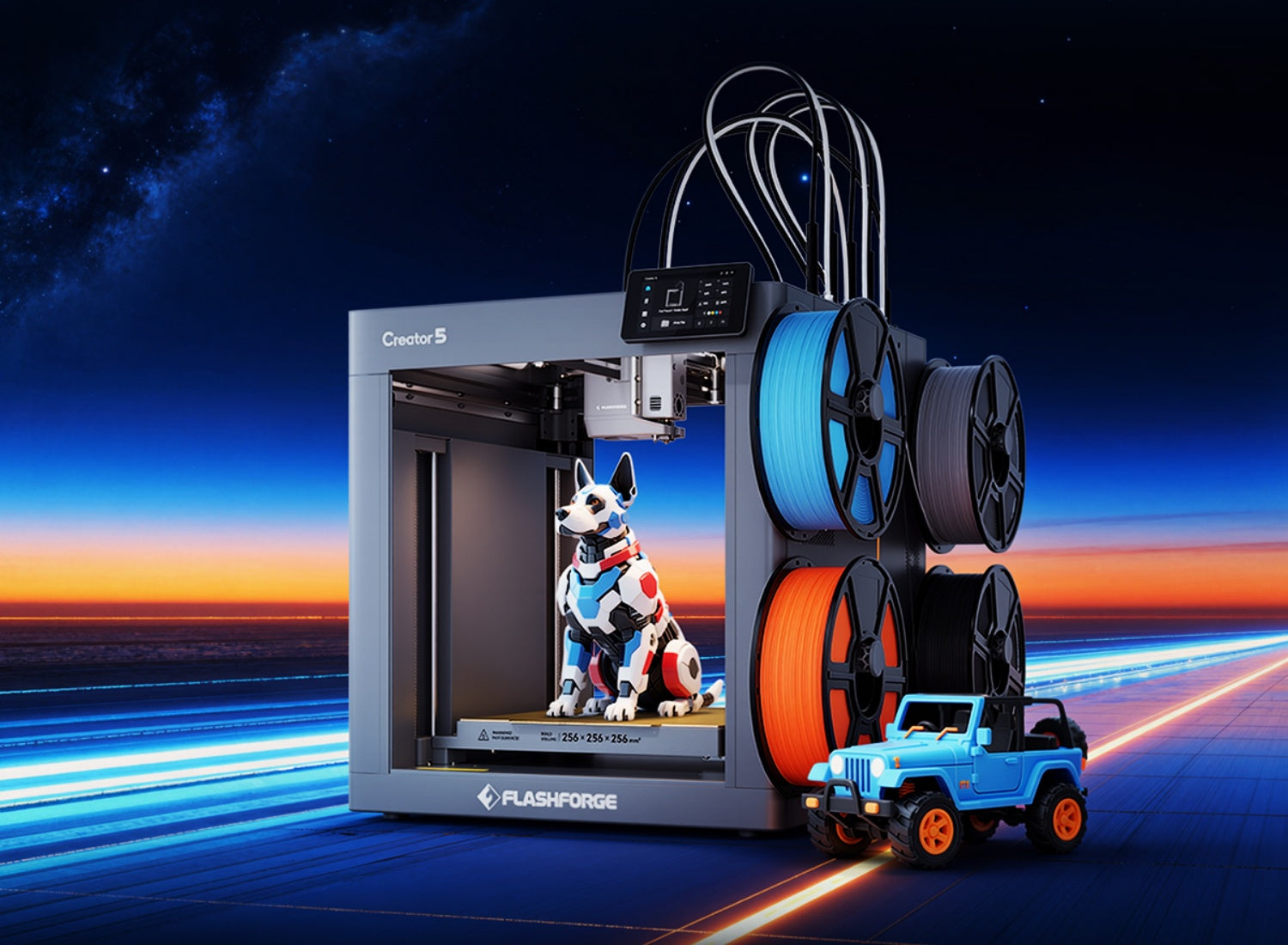
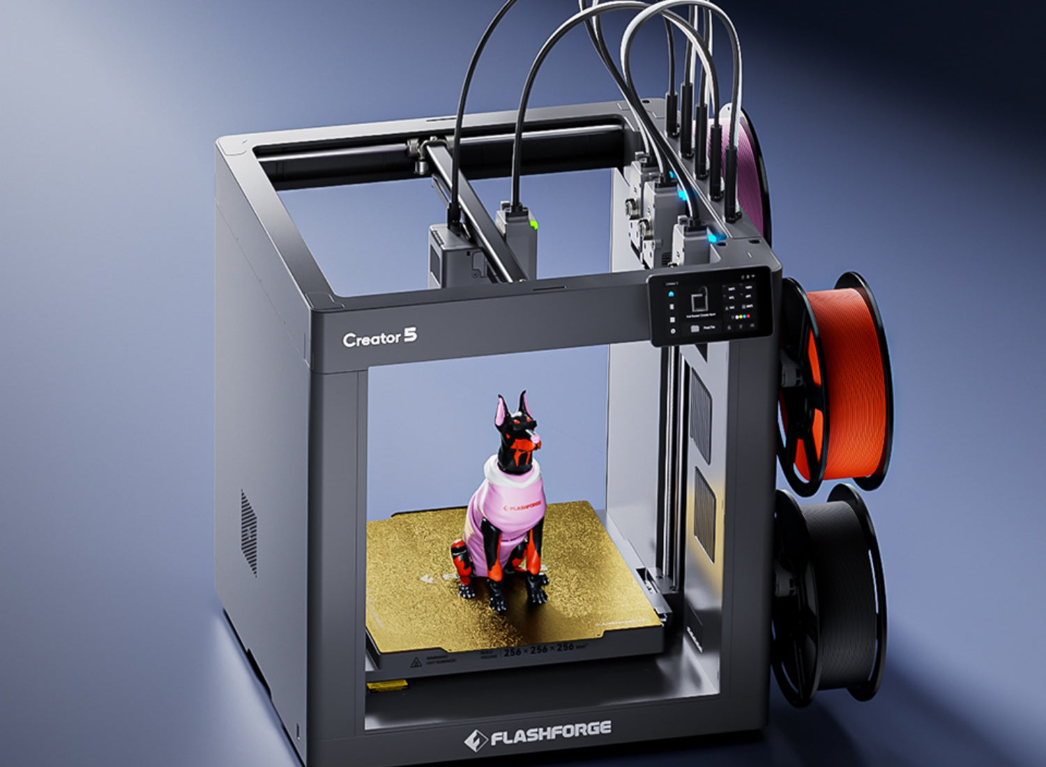
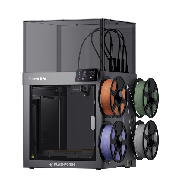
Geometry is only half the story when you want to reduce material waste. The printer's filament-switching method also matters. Tool-changing designs such as the Flashforge Creator 5 (C5) use four independent toolheads and avoid purge waste during material switching. This makes the C5 relevant for multi-color models where frequent filament changes would otherwise consume additional material.
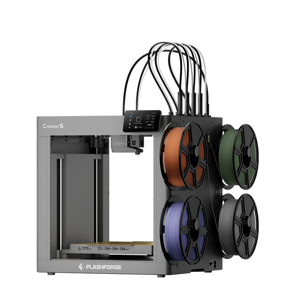
Flashforge Creator 5 4-Toolheads Multi-Color 3D Printer | 500% Faster, Zero Purge Waste
How Should You Export a 3D Model for 3D Printing?
Exporting is not an administrative step. A poor export can damage an otherwise good design.
Before exporting, confirm that the units are correct, the scale matches the intended object, and the geometry is solid. Separate parts should remain separate when required. Multi-color bodies should be clearly defined. Hidden surfaces and accidental objects should be removed.
STL vs OBJ vs 3MF File Formats
STL, OBJ, and 3MF are common file formats, but they do not carry the same information.
| File Format | Best Use | Main Strengths | Main Limitations |
| STL | Basic single-material geometry | Widely supported and easy to export | Limited metadata and no color or material information |
| OBJ | Visual models and mesh exchange | Can support visual information in some workflows | Not designed specifically for additive manufacturing |
| 3MF | Modern 3D printing workflows | Can preserve scale, model data, color, materials, and manufacturing information | Requires compatible software support |
The 3MF Consortium FAQ explains that STL does not contain color or material-property information. The official 3MF specification was developed for additive manufacturing and can preserve a broader range of model data.
STL remains useful for simple single-material models. OBJ may be suitable when a workflow requires visual mesh information. For multi-color or multi-material projects, 3MF is often the more practical option because it can preserve more information in one file.
Setting Export Resolution and Avoiding Common Mistakes
Mesh export resolution controls how accurately curved surfaces are converted into triangles.
A low-resolution export can make circles appear faceted and curves look rough. An unnecessarily high-resolution export can create large files and slow down slicing without improving the printed result.
Use a moderate mesh resolution for basic functional parts. Increase the resolution for curved surfaces and detailed display models. Avoid excessive polygon counts on flat areas. Inspect circles, arcs, and rounded corners after export.
Several mistakes can create print problems. Incorrect units can make a model import too large or too small. Non-manifold geometry can prevent the slicer from reading the object correctly. Hidden objects may appear unexpectedly on the build plate. Thin details may disappear after slicing. Incorrect surface normals can create missing or inverted areas.
Always import the exported file into the slicer and inspect it before printing.
How Do You Prepare a 3D Model in Slicer Software?
A slicer converts the model into printable instructions. This is where you decide how the printer should build the object.
The slicer needs information about the printer, nozzle, filament, layer height, supports, infill, and build-plate arrangement.
Importing and Orienting Your Model
Import the STL, OBJ, or 3MF file into the slicer. Use a printer profile that matches the exact machine and nozzle size. Then choose the filament type and process preset.
Confirm that the scale is correct, the object fits within the build volume, and the model rests properly on the build plate. Separate bodies should appear as intended. Review any warning messages before slicing.
Choose the orientation according to strength, surface quality, support requirements, and print time. Place visible surfaces away from support contact points. Position functional parts so the layer lines do not create an obvious failure point.
Scale the object only when necessary. When exact dimensions matter, return to the CAD file and correct the source model rather than resizing it casually in the slicer.
Choosing Layer Height, Infill, and Previewing Toolpaths
Layer height affects surface quality and print time. A lower layer height can improve detail and reduce the stepped appearance of curves. A higher layer height can shorten printing time for simple prototypes and large objects.
Infill supports the internal structure of the model. A quick concept print may need limited infill. A functional bracket may require additional internal support and stronger walls. A decorative object may need enough infill to support its outer surfaces without adding unnecessary weight.
Infill alone does not determine strength. Wall thickness, perimeter count, filament, orientation, and geometry also matter.
Preview the sliced model layer by layer before sending it to the printer. Check the following areas:
-
First-layer contact and support placement
-
Bridges, overhangs, and thin walls
-
Internal cavities and infill continuity
-
Travel paths, color changes, and material changes
-
Unexpected gaps and estimated print time
A toolpath preview helps identify problems that are difficult to see in the original CAD file. A small opening may disappear after slicing. An unsupported section may begin in mid-air. A wall may be too thin for the selected nozzle.
Best Practices for Different Types of 3D Printed Models
Different applications require different modeling priorities. A bracket, resin miniature, wearable prop, and product-development prototype should not follow the same design workflow.
Functional Mechanical Parts
Functional parts need measurable performance.
Start with dimensions, load direction, connection points, and operating conditions. Add reinforcement where force concentrates. Print small test coupons before producing the full component.
Accurate dimensions, suitable wall thickness, realistic clearances, strong layer orientation, and real-world testing all matter. Avoid sharp internal corners where stress may concentrate. Add fillets or ribs where they improve strength. Use chamfers where parts need to slide together.
Miniatures and Resin Models
Miniatures prioritize detail, surface finish, and support placement.
Use clean geometry and avoid details that are too small to survive printing or post-processing. Place supports away from visible surfaces. Test delicate features such as fingers, horns, thin edges, and narrow decorative details.
The Flashforge resin vs filament guide explains that resin printing is more suitable when fine detail and smooth surfaces are the main priorities. FDM printing remains more accessible for practical parts and larger objects.
For hollow resin models, plan suitable drainage openings and follow the instructions for the selected printer and resin. Do not transfer FDM wall-thickness assumptions directly to resin models.
Wearable and Cosplay Designs
Wearable models need to fit the body, survive handling, and remain practical to assemble.
Begin with accurate measurements or reference geometry. Add clearance for padding, straps, clothing, and movement. Divide large designs into sections with hidden seams and strong alignment features.
Test the fit with a draft print before producing the complete object. Place seams where sanding is manageable. Reinforce high-stress joints. Leave room for straps and padding. Check visibility, ventilation, and total weight before printing the final version.
Prototypes for Product Development
A prototype should answer a specific question.
A rough model may confirm external dimensions. A second version may test component fit and assembly. A later sample may evaluate material performance, ergonomics, or surface appearance.
Do not add every final detail at the beginning. Start with the feature you need to test. This makes each iteration faster and easier to evaluate.
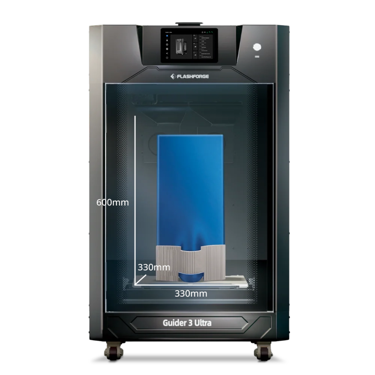
For ABS and selected carbon-fiber-reinforced filaments, temperature control becomes part of the workflow. The Flashforge Creator 5 Pro (C5P) combines four independent toolheads with a fully enclosed frame and an actively heated chamber up to 65°C. Its official specifications also list broader material support, including PC, PA, PC-ABS, and PPS-CF for enclosed printing. These features make it relevant for engineering-material prototypes and multi-material concept validation.
Flashforge Creator 5 Pro 4-Toolheads Enclosed Multi-Color 3D Printer | 500% Faster, Zero Purge Waste
Conclusion
Learning how to create 3D models for printing starts with a practical mindset. A printable file needs more than an attractive shape. It needs accurate dimensions, solid geometry, suitable wall thickness, and a structure that matches the printing process.
Begin with simple forms. Measure carefully. Test clearances. Reduce unnecessary supports. Split large models when needed. Choose the correct export format. Inspect the mesh and preview every sliced layer before printing.
The best workflow depends on the project. Functional parts require strength and tolerances. Miniatures need detail and careful support placement. Wearable designs need fit and assembly planning. Product prototypes need fast iteration and clear testing goals.
A well-designed model reduces failed prints, saves material, and makes the final result easier to produce consistently.
FAQ
How much does it cost to run a 3D printer for 1 hour?
The cost depends on the printer's actual power draw and your local electricity rate.
The Flashforge guide to 3D printer electricity use states that mainstream desktop FDM printers commonly use 50 to 250 watts during a print job. Small to medium hobby models often stay within the 50 to 150 watt range.
The U.S. Department of Energy provides the calculation method:
Hourly cost = Power draw in watts ÷ 1,000 × Local electricity rate per kWh
For example, a printer drawing 100 watts at an electricity rate of $0.18 per kWh costs about $0.018 per hour. Actual usage changes with the heated bed, nozzle temperature, filament, chamber temperature, and print duration. A plug-in energy monitor gives a more accurate figure for a specific setup.
How to set up a 3D model for printing?
Start with a complete, manifold model. Confirm the dimensions, wall thickness, clearances, and orientation. Export the design in a suitable format such as STL or 3MF. Import it into the slicer, select the correct printer and filament profile, add supports where needed, and preview the toolpaths before printing.
Why do 3D printers have so much waste?
Waste usually comes from supports, brims, rafts, failed prints, test pieces, and post-processing. Multi-color printing can also create purge waste when a single nozzle needs to clear the previous filament before switching colors.
Waste can be reduced by designing support-friendly geometry, selecting an efficient orientation, validating the sliced toolpath, and using only the infill required for the application. Tool-changing systems can also reduce purge waste during multi-color printing.
What do I need to start 3D printing for beginners?
A beginner needs a suitable 3D printer, compatible filament or resin, slicer software, a printable model file, and a stable workspace. Basic tools such as calipers, a scraper, and cleaning supplies can also help.
Start with a simple model and a standard filament. Learn how to import the file, select a profile, slice the model, preview the toolpath, and inspect the finished print. More complex materials and assemblies can come later.