


A 3D model can look perfect on screen and still fail in the slicer or on the print bed. Thin walls, unsupported overhangs, poor orientation, and tight fits often cause weak parts or assembly problems. Good design starts with the printer, material, and intended use in mind.
What to Prepare Before Designing a 3D Print
Before modeling, decide what the part must do, how it will be printed, and which material it needs. When comparing a 3d printer for sale, check that its build volume, nozzle options, and material support match your projects rather than focusing only on price.
Define the Model’s Purpose and Performance Needs
A decorative model mainly needs a stable base and clean surfaces. A bracket, enclosure, hinge, or replacement part must also withstand force, movement, or heat.
Identify where loads will enter the part, which areas must flex, and where screws or inserts will be installed. Reinforce those points with ribs, fillets, or thicker bosses instead of adding infill everywhere.
The best 3d printer for a project is not simply the fastest or largest model. It should match the required material, part size, detail level, and working environment.
Measure Key Dimensions and Plan the Assembly
Use digital calipers when a model must fit an existing object. Record overall size, wall thickness, hole diameter, spacing, and connector positions.
Choose a reference plane or centerline so related features remain aligned. Plan the assembly method before adding small details.
Choose the Right Printing Process and Material
FDM printing suits enclosures, tools, fixtures, toys, and larger functional parts. Resin printing is better for miniatures and fine details but requires washing and curing.
PLA works well for visual prototypes, PETG suits tougher functional parts, and TPU is useful for flexible grips or seals.
For designs that combine colors, rigid and flexible areas, or dedicated support materials, separate those regions into different bodies. The Flashforge Creator 5 is a high speed 3d printer with four independent toolheads and a 256 × 256 × 256 mm build volume. Different bodies can be assigned to separate colors or materials before slicing.
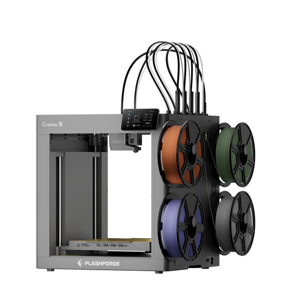
Flashforge Creator 5 4-Toolheads Multi-Color 3D Printer | 500% Faster, Zero Purge Waste
Confirm the Printer’s Build Volume and Nozzle Size
Make sure the model fits inside the usable build area of your 3d printer after rotation, brims, and supports are added.
The Flashforge Adventurer 5M has a 220 × 220 × 220 mm build volume and supports 0.25, 0.4, 0.6, and 0.8 mm nozzles. Smaller nozzles suit fine text and small features, while larger nozzles are better for thick walls, large parts, and faster printing.
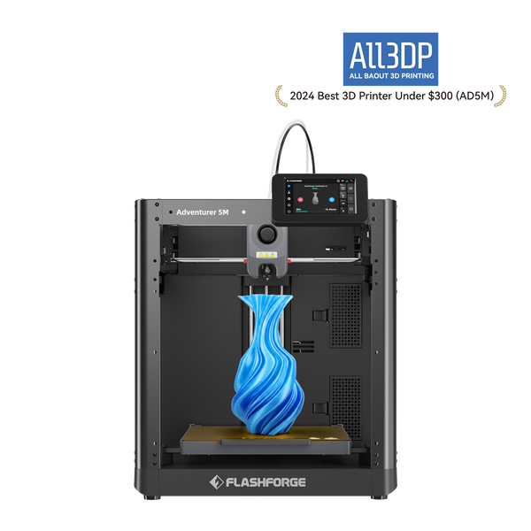
Imprimante 3D Flashforge Adventurer 5M, vitesse élevée de 600 mm/s, adaptée aux débutants
How to Design a 3D Print Step by Step
A reliable workflow moves from simple geometry to functional details.
Step 1: Set the Units, Scale, and Main Dimensions
Set the document units before modeling. Millimeters are standard in most desktop workflows. Define the overall dimensions first, then add reference planes and mounting surfaces.
Avoid scaling functional parts in the slicer because scaling also changes holes, clearances, threads, and wall thickness.
Step 2: Create a Simple Base Shape
Start with the simplest solid that describes the object. A case may begin as a box, a knob as a cylinder, and a bracket as a plate with one flange. Check the main dimensions before adding decorative details.
Step 3: Add Holes, Connectors, and Functional Features
Add screw holes, cable openings, clips, hinges, pins, and joining surfaces after the main body is stable.Design each feature around its use. Cable openings may need chamfers, screw bosses with wider bases, and snap-fits with enough flexible length to bend without cracking.
Step 4: Set Wall Thickness and Assembly Clearance
Wall thickness should match extrusion paths. With a 0.4 mm nozzle, walls around 0.8, 1.2, or 1.6 mm often slice predictably because they can be formed by continuous perimeter lines. Load-bearing areas may need thicker walls or local reinforcement.
Different types of 3d printer filament vary in shrinkage, stiffness, flexibility, and dimensional stability, so the same wall thickness or gap may behave differently across materials.
Fitted parts also need clearance. A test coupon with several gaps provides a practical starting point. The correct value depends on the printer, material, nozzle, orientation, and required fit.
Step 5: Adjust Overhangs, Bridges, and Print Orientation
Orientation affects strength, finish, support marks, print time, and bed contact. Keep important cosmetic surfaces away from support.
For functional parts, orient the model so normal forces do not pull directly across layer lines. Sometimes the strongest orientation uses more support, so balance strength against cleanup and surface quality.
Step 6: Split Large or Complex Models When Needed
Splitting a model can reduce support, improve orientation, fit the part within the build volume, and simplify reprinting.Place seams where they can be hidden or reinforced. Add alignment pins, tabs, dovetails, or broad bonding surfaces before separating the bodies.
Step 7: Export and Inspect the Model in the Slicer
Check for open surfaces, overlapping bodies, reversed faces, internal geometry, and non-manifold edges before export.
STL works well for simple geometry. According to the 3MF Consortium, 3MF can preserve units, colors, materials, and relationships between multiple objects.
After import, inspect the layer preview. Confirm that thin walls appear, holes remain open, and no section starts in mid-air. Flashforge’s guide to Orca and Orca-Flashforge explains the slicing and toolpath workflow.
Three Essential Rules That Make a Model Printable
These rules solve many common design problems.
Rule 1: Use the 45-Degree Rule as a Starting Point
A surface around 45 degrees from vertical can often print without support because each layer overlaps the one below it. Flatter undersides are more likely to sag.
Treat 45 degrees as a guideline, not a fixed limit. Cooling, filament, speed, layer height, and feature length all affect the result.
Rule 2: Use Slopes, Arches, and Split Parts to Reduce Support
Replace flat unsupported ceilings with chamfers, arches, teardrop openings, or angled roofs. These shapes let each layer rest more securely on the previous one.
When the geometry cannot be made self-supporting, split the model and print each section in a better orientation.
Rule 3: Match Wall Thickness to Extrusion Width
A wall that exists in CAD may disappear in the slicer if it is too thin or cannot be represented by a stable extrusion path.
Use values that work with the selected nozzle and inspect the preview. Check whether the slicer creates continuous perimeter lines.
Common Mistakes to Avoid When Designing 3D Prints
Many print failures begin with design choices.
Increasing Infill While Ignoring Walls
Ignoring Layer Direction
FDM parts are direction-dependent. A hook or bracket may be strong along printed lines but weaker between layers.Orient the model so the expected force does not peel layers apart. If the strongest orientation creates difficult supports, revise the geometry or split the part.
Leaving No Clearance
Two mating parts designed at the same size are unlikely to move freely after printing. Surface texture, first-layer compression, and extrusion width reduce the available space.
Use different clearances for press fits, sliding fits, rotating joints, and glued assemblies.
Designing Holes, Threads, and Snap-Fits at Exact Size
Printed holes may come out smaller than their CAD diameter, especially when they are horizontal. Add chamfers, lead-ins, or several test diameters.
For parts assembled repeatedly, threaded inserts or standard fasteners may be more durable than small printed threads.
Using Too Much Support
Support increases print time, material use, cleanup, and surface damage. Before enabling it everywhere, revise unsupported areas.
A chamfer, arch, different orientation, or split may remove the need for support.
Skipping Test Prints
Do not print a full enclosure just to test one snap-fit. Crop the critical area and print it with the final material, nozzle, layer height, and orientation.
Flashforge’s guide to editing STL files is useful when a downloaded model needs repair, cutting, or dimensional changes.
Final Checklist Before Printing
Before starting the full model, confirm:
-
The geometry is closed and free of non-manifold edges.
-
Units, scale, and final dimensions are correct.
-
The model fits the printer’s build volume.
-
Walls and small features appear in the layer preview.
-
Orientation balances strength, finish, and bed contact.
-
Overhangs and bridges are printable or supported.
-
Assembly clearances and hole positions are correct.
-
Multi-color or multi-material bodies are assigned correctly.
-
Critical fits, threads, and snap-fits have been test printed.
Conclusion
Learning how to design 3D prints means thinking beyond the shape on screen. A successful model must match the printer, material, nozzle size, layer direction, and final use.
Start with accurate dimensions and simple geometry. Add functional details first, use realistic wall thickness and clearance, reduce unnecessary support, and inspect the sliced toolpaths.
FAQ
What Is the Best 3D Modeling Software for Beginners?
Tinkercad is one of the easiest options for simple models made from basic shapes. Parametric CAD software is better for precise functional parts, while sculpting tools suit characters and organic forms.
Can You Edit a Downloaded STL File?
Yes. STL files can be scaled, cut, combined, repaired, or modified in a mesh editor. Major functional changes are easier when the original CAD file is available because STL files do not contain the original design history.
Should You Export as STL or 3MF?
Use STL for broad compatibility and simple geometry. Use 3MF when the project includes multiple bodies, colors, materials, or defined units.
Can the Same Model Be Used for FDM and Resin Printing?
The same source model can be adapted for both, but each process needs different preparation. FDM design must consider nozzle width, bridging, and layer strength, while resin models may require hollowing, drainage holes, and different supports.
Why Does My Model Look Fine in CAD but Show Errors in the Slicer?
The model may contain open edges, zero-thickness surfaces, reversed faces, overlapping bodies, or internal geometry. Repair the source model and review the affected layers again.