


Custom cut-outs let a 3D printed case accommodate ports, switches, screens, fans, cameras, buttons, and cables without requiring a complete enclosure redesign. The process usually involves measuring the physical component, drawing the opening, subtracting it from the case, and printing a small test section.
The modeling operation is rarely the difficult part. Most fit problems come from inaccurate measurements, insufficient clearance, poor positioning, or weak walls around the opening.
Plan the Cut-Out Before Editing the Case
Start with the physical component. Check not only its visible dimensions but also the space needed for mounting clips, wiring, circuit boards, and cable movement.

Decide What the Cut-Out Needs to Fit
The shape of the opening depends on the component and how it will be installed. A fixed cable may need only a round hole, while a panel-mounted switch requires space for its body, clips, and rear terminals.
Usage also affects the design. A charging port used every day benefits from extra room for fingers and the connector housing. A permanently installed cable can use a smaller opening with a grommet.
Measure the Part and Its Position
Use digital calipers to measure the component’s width, height, diameter, flange, corner radius, and mounting features. Then locate it from two stable reference surfaces, such as the bottom and side of the enclosure.
When several ports belong to one circuit board, reference them from the board mounting holes instead of measuring each opening separately. This keeps USB, HDMI, and power ports aligned with the actual hardware.
Add Clearance for Real-World Fit
An opening modeled at the exact size of the component may print too tight. Because fdm 3d printing builds parts layer by layer, extrusion width, cooling, material shrinkage, calibration, and orientation can affect the final dimensions.
As a starting point, add about 0.2 to 0.3 mm per side for a close fit. Parts that need to slide in easily may require 0.4 to 0.6 mm per side. These values should be confirmed with a small test print rather than treated as universal rules.
Research into FDM dimensional tolerances also shows that machine calibration and process settings influence assembled fits. See this study on FDM dimensional tolerance and fit.
Check the Wall Thickness Around the Opening
A cut-out can weaken the case when it sits near a screw boss, hinge, snap joint, or corner. Leave enough material around the opening and use rounded internal corners where possible.
For example, placing a cable hole directly beside a mounting screw may leave a narrow strip of plastic that cracks when the screw is tightened. Moving the opening slightly or adding a reinforcing rib is usually more effective than increasing infill.
Choose the Best Method for Creating the Cut-Out
The best method depends on the source file and the precision required. The workflow may be similar across different 3d printer models, but material, nozzle size, and orientation still affect the final design.
Edit the Original CAD Model When Available
The original CAD file is the best option because it preserves dimensions, constraints, wall features, and design history. You can move or resize the opening later without rebuilding the enclosure.
This approach is especially useful for cases with aligned ports, mounting screws, snap fits, or replaceable panels. Flashforge’s article on how to create 3D models for printing also explains how wall design, geometry, orientation, and export settings affect printability.
Use Boolean Subtraction to Cut the Opening
Boolean subtraction works well for most cut-outs. Create a solid that represents the empty space required by the component, extend it through the wall, and subtract it from the case.
Use a box for rectangular ports, a cylinder for round holes, or a custom body for irregular shapes. Extend the cutting solid slightly beyond both wall surfaces to avoid leaving a thin internal skin.
Edit an STL When the Original File Is Missing
An STL can be modified, but it contains mesh triangles rather than editable dimensions. Simple holes and slots are manageable, while repeated or highly precise revisions are more difficult.
Inspect the file for open edges, inverted faces, and internal surfaces before editing. Flashforge’s article on how to edit STL files covers mesh repair, geometry changes, and export checks.
Create a Custom Shape for Irregular Parts
Keyed connectors, rocker switches, locking tabs, and angled cable entries may require a custom sketch. Reproduce the features that affect installation, but avoid adding tiny cosmetic details that the nozzle cannot print reliably. A snap-in switch, for example, needs an opening for its main body plus enough room for the side clips to compress during installation.How to Add a Custom Cut-Out Step by Step
Keep the feature editable until the fit has been tested. This makes it easier to correct the size or position without rebuilding the model.

Step 1: Import or Open the Case Model
Open the CAD file or import the STL into a suitable editor. Confirm the units and compare one known dimension with the real enclosure. Save an unmodified copy before making changes.
Step 2: Create a Reference Plane or Sketch
Select the wall where the opening will be placed. Flat walls can usually be sketched directly, while angled or curved surfaces may require a reference plane. Project nearby edges, mounting holes, or centerlines into the sketch to control the opening’s position.
Step 3: Draw the Cut-Out Shape
Draw the opening using the measured size plus the selected clearance. Add dimensional constraints so the shape remains easy to adjust. Include important corner radii and keyed features, but keep the geometry appropriate for the selected nozzle.
Step 4: Extrude the Shape Through the Case Wall
Extrude the sketch completely through the wall. A through-all or symmetric cut is often more reliable than entering the exact wall thickness.
Step 5: Apply the Boolean Cut
Subtract the cutting body and inspect the opening from both sides. Check for leftover faces, damaged ribs, thin borders, or accidental cuts into nearby mounting features.
Step 6: Add Fillets, Chamfers, or Reinforcement
Chamfers can guide connectors into place, while fillets reduce stress at sharp corners. Frequently used ports may also need a thicker border or reinforcing rib.
Creator 5 Series for Rigid and Flexible Case Parts
Chamfers can guide connectors into place, while fillets reduce stress at sharp corners. Frequently used ports may also need a thicker border or reinforcing rib, especially when plugs will be inserted and removed repeatedly.
Material transitions should also be considered at this stage. A rigid case may include flexible cable grommets, seals, feet, or impact-resistant bumpers. Instead of designing and assembling each component separately, these features can be incorporated into the same model and produced with compatible rigid and flexible filaments.
For this type of soft-and-rigid enclosure, the Flashforge Creator 5 uses four independent toolheads, allowing rigid materials and TPU parts to be assigned to separate toolheads within one print. Its 256 × 256 × 256 mm build volume also provides enough space for many desktop enclosures and control boxes.
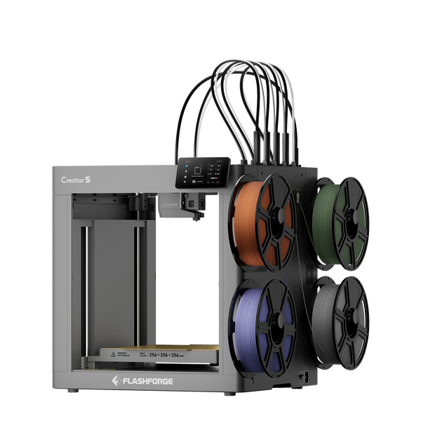
Flashforge Creator 5 4-Toolheads Multi-Color 3D Printer | 500% Faster, Zero Purge Waste
Material selection should still match the enclosure’s working environment. If the case will be exposed to heat or printed in ABS, compare enclosure design, chamber control, bed temperature, and material compatibility when choosing an abs 3d printer. For more temperature-sensitive materials, an enclosed machine such as the Creator 5 Pro provides more controlled conditions than the open-frame Creator 5.
Step 7: Export and Inspect the Model
Before starting 3d printing, export the case as an STL or 3MF file and inspect the sliced layers. Check thin walls, horizontal openings, bridges, and narrow slots. Make sure automatic mesh repair has not closed the opening or removed an intended feature.
Do not print the complete enclosure for the first fit check. Instead, crop a small section containing the opening and enough surrounding wall to reproduce the final geometry. For example, a panel-mounted switch opening can be tested with several clearance values on one small plate, using less filament and providing feedback much faster than a full-case print.
This type of repeated fit testing is easier on a machine with a simple setup. The Flashforge Adventurer 5M combines automatic leveling, quick-detach nozzles, a CoreXY structure, and a 220 × 220 × 220 mm build volume, making it a practical 3d printer for beginners who need to test ports, clips, and mounting features before printing the final enclosure.
Common Cut-Out Problems and How to Fix Them
Compare the printed opening with the CAD model before changing multiple settings. First, identify whether the problem comes from dimensions, positioning, orientation, or wall strength.
The Opening Is Too Small
Measure the opening at several points. If the difference is consistent, enlarge the CAD feature slightly or apply a tested slicer compensation value. Use the same material, nozzle, orientation, and layer settings when comparing test prints.
The Opening Is Too Large
A slightly oversized opening may be corrected with a gasket, bezel, or flexible insert. For a cleaner result, reduce the CAD dimensions and print another test section. Remember that 0.4 mm of clearance per side increases the total opening by 0.8 mm.
The Cut-Out Is in the Wrong Position
Recheck the reference dimensions instead of moving the opening by eye. Use board edges, screw holes, or mounting bosses as shared datums. When several openings belong to the same component, position them from one common reference system.
The Edges Look Rough or Sagged
The upper edge of a horizontal opening may act as a bridge. Changing the print orientation may solve the problem without altering the model.
Other options include adding a chamfered top, shortening the unsupported span, improving cooling, reducing bridge speed, or applying limited support. Research into factors affecting 3D printed holes also shows that orientation and print settings influence dimensional accuracy.
The Case Cracks Around the Opening
Cracks usually mean the surrounding wall is too narrow or the insertion force acts across weak layer lines. Increase the border, round the corners, add local thickness, or connect the area to a stronger section with ribs. Snap-in components also need enough clearance for their clips to flex without forcing the case apart.
Conclusion
A reliable custom cut-out starts with accurate measurements and stable reference points. Add suitable clearance, protect the remaining wall, and consider how the part will be installed and used.
Edit the original CAD model when possible, use Boolean subtraction for clean openings, and print a small test section before producing the full enclosure. This simple check can reveal fit, alignment, and edge-quality problems while using much less time and filament.
Frequently Asked Questions
How Much Clearance Should I Add Around a 3D Printed Cut-Out?
Start with about 0.2 to 0.3 mm per side for a close fit or 0.4 to 0.6 mm per side for easier insertion. Confirm the value with a test print.
What Is the Best Software for Adding Cut-Outs to an STL File?
Use software that can repair meshes, create cutting solids, perform Boolean operations, and export manifold geometry. Parametric CAD is usually better for repeated or dimensionally critical revisions.
How Do I Make a Hole in a 3D Model?
Create a cutting body, extend it through the model, and subtract it with a Boolean operation. Inspect the remaining wall and sliced layers before printing.
Why Are My 3D Printed Holes Smaller Than the CAD Model?
Extrusion width, cooling, material shrinkage, seam buildup, calibration, and print orientation can make holes smaller than their CAD dimensions.
Should I Print the Entire Case to Test a Cut-Out?
No. Print only the section containing the opening and nearby wall. It is faster, uses less material, and makes clearance comparisons easier.